How Microwave Absorbers Eliminate RF Noise
The increase in the number of electronic devices in the marketplace has cultivated the rise of electromagnetic interference (EMI) issues with unpredictable and troublesome effects. This has brought an inevitable hardship to design engineers and the challenges they face as today’s electronic equipment becomes thinner and multifunctional (e.g., smartphone, GPS, wireless LANs). Although the EMI can be reduced by a proper PCB design, RF noise remains one of the most difficult tasks facing design engineers.
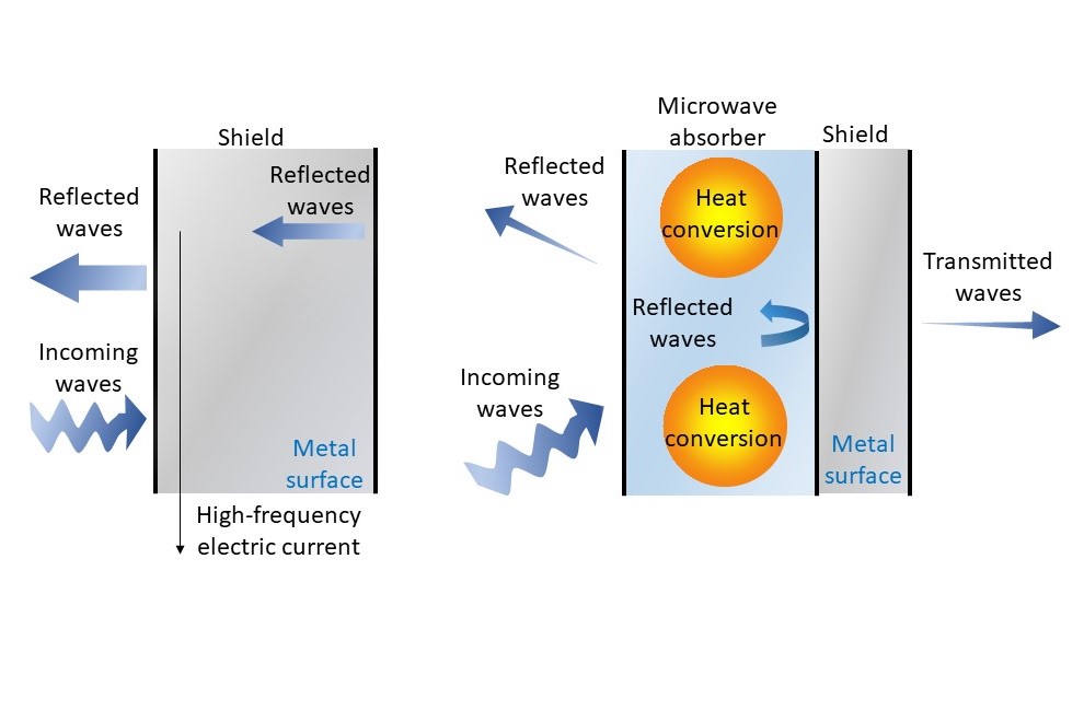
To eliminate the RF noises, shielding with conductive material (e.g., shielding can, conductive gasket) is the most common technique used today. It envelops the noise source, increases the grounding level, and suppresses the radiated noise. However, present-day electronic devices operate at hundreds of MHz with harmonic emissions in GHz region. The reflected high-frequency signal in a conductive shielding system can cause severe problems to the shielded device itself or other adjacent electronic components. Furthermore, a highly integrated electronic system can create more complex RF issues that cannot be eliminated with simple shielding and grounding techniques (Fig. 1).
As a result, we at Schlegel Electronic Materials (SEM) have developed the BandSorb® microwave absorbing materials whose range of electrical and magnetic properties allow attenuation of noise from 5 MHz to 40 GHz. These materials can be easily integrated into very tight spaces.

Microwave Absorption Theory
Microwave absorbers are a composite material that consists of dielectric and magnetic fillers inside a polymeric matrix. These fillers modify the relative complex permittivity and permeability of the base material, governing the microwave absorber’s key parameters.
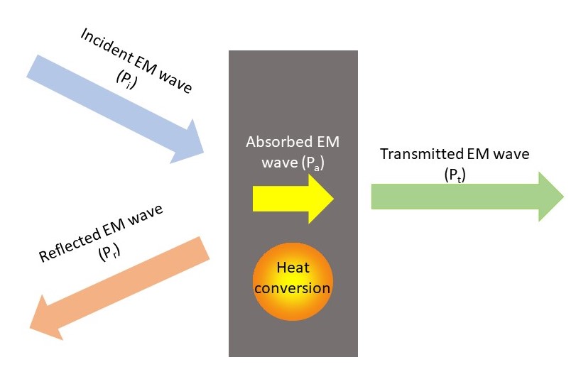
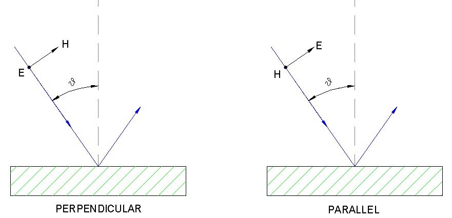
When the electromagnetic (EM) waves propagate through a microwave absorber, not all the energy is absorbed; part of it is reflected or transmitted (Fig.2). Polarization of the dielectric component of the microwave absorber by the electric field (E) of EM waves gives rise to the relative complex permittivity, ɛ* = ɛ’ – jɛ”. The real part of the dielectric constant ɛ’ refers to the storage capability of the EM wave energy while the imaginary part of the dielectric constant ɛ” indicates the extent of attenuation of the electric field by the microwave absorber. The ratio of the imaginary to the real part affords the electric loss tangent, tan⸹e = ɛ”/ɛ’ which denotes the energy loss in the microwave absorber. The greater the loss tangent, the higher the attenuation of EM waves.
Similarly, the interaction of the magnetic component of the microwave absorber with the magnetic field (H) of EM waves derives the relative complex permeability µ*=µ’-jµ” and the ratio of the imaginary to the real part defines the magnetic loss tangent tan⸹m = µ”/µ’. As the electric field and magnetic field are coupled in EM waves, energy loss in either field will attenuate the energy in EM waves. Therefore, knowing the complex permittivity and permeability over a frequency range allows one to determine the attenuation which is given by:


Download our Free EMI/RF Absorber Reference Guide to read the rest of this article.
It includes:
- Microwave Absorption Theory
- Solutions Across a Wide Range of Applications
- BandSorb® SC, ST, SN, HP, and FB
- Series with Datasheet for Performance Characteristics
- Absorber Materials Selection Guideline

Download for Free
BandSorb® elastomer absorbers by Schlegel Electronic Materials, a leader in the design, development, and manufacturing of EMI/RF absorber materials.
Explore our robust line of high-performance absorber products. Any size designs with our quality assurance. Our standard quality control process gives Schlegel the unique capability to offer measurement, ensuring every product that leave our facility meets your requirements.
