Cavity resonance suppression at 24.5 GHz
Introduction:
Modern electronic devices are working at increasing frequencies and require a high level of separation of signals for different parts of the device. Failing to provide the correct level of separation will lead to an underperforming system.
Typically shielding is used to separate the different parts of the circuit. The lack of sufficient foot print to separate the different parts and the occurrence of cavity resonance can put the use of shielding to its limits.
A short range automotive radar working at 24 GHz is a typical example of such a system.
In this document we will provide an effective way to dampen cavity resonances with BandSorb® and avoid EMI leakages.
BandSorb® SC consists of a thin flexible high-loss, magnetically loaded and electrically non-conductive silicone rubber.
Test structure:
Figure 1 provides a block diagram of a typical system consisting out of 2 patch antennas situated on one side of the PCB, and the Transmit (TX) and Receiver (RX) electronic components sitting on the opposite side.
To get a high sensitivity of the system one needs to avoid that EMI will leak from:
– The electronics on the bottom side of the PCB to the top side of the PCB.
– TX to RX electronics.
In many cases a shield is placed over the electronics to avoid EMI leakage occurring from the bottom electronics.
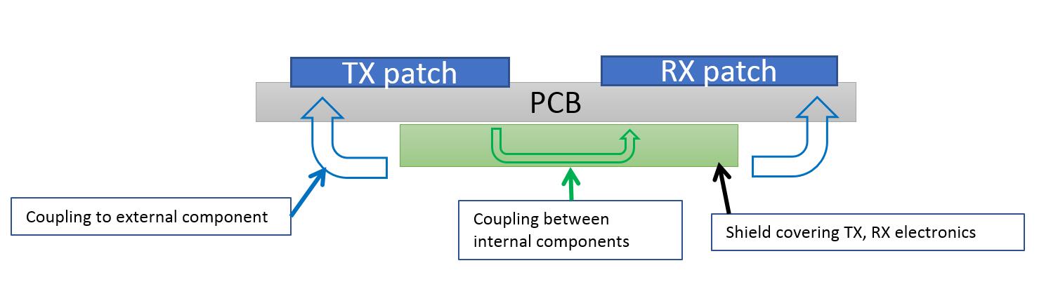
Figure 1: Block diagram
In this study we will make use of the simplified structure consisting of one external patch, a structure that radiates the EMI and a disturbed structure situated in the shield, given in Figure 2.
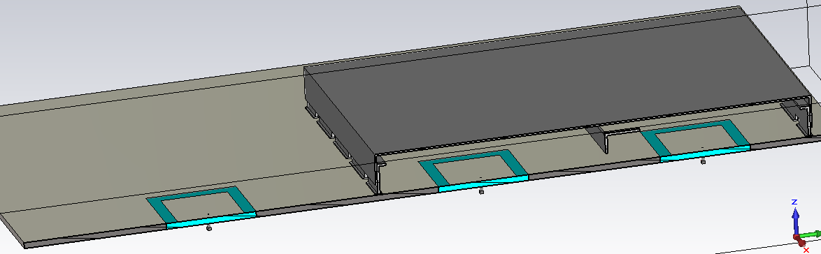
Figure 2: Simplified structure
The open shield case
If no shield is applied over the radiator of unwanted energy we can see in the E-Field distribution of Figure 3 that energy will be coupled to the patch antenna.
Figure 3: Open shield case
To overcome this problem a shield is placed over the radiator of EMI.
In Figure 4 we can see that the shield removes the EMI from coupling between the un-intended radiator and the external part.
Also in Figure 4 we can also see that at 24.5 GHz a cavity resonance occurs that causes the shield not to function as required. Apart from this we can also see a high coupling of energy (Green) between the 2 internal parts of the shield.
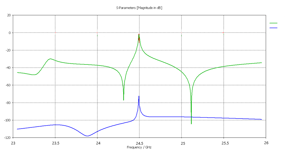
Figure 4: Closed shield (green: internal coupling, blue: external coupling)
BandSorb® SC-31
BandSorb® SC is a magnetically loaded, electrically non-conductive silicone rubber. When placed on the inside of a microwave cavities BandSorb® SC series will reduce the Q of the cavity, eliminate surface currents and generally dampen reflections.
In our example a BandSorb® SC-31 of 0.5 mm is placed on the lid of the shield to suppress the cavity resonance.
In Figure 5 we can see that the BandSorb® SC-31 removed the high internal coupling at the resonance frequency. In addition the shielding performance is improved at the resonance frequency.
The field distribution given in Figure 6 shows that BandSorb® SC-31 material effectively can be used to remove cavity resonances.
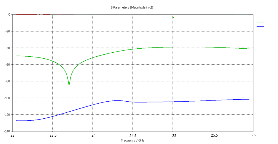
Figure 5: Closed shield + BandSorb® SC-31 (green: internal coupling, blue: external coupling)
Figure 6: Closed shield + BandSorb® SC-31 E- Field distribution
Conclusion
In this study we showed that BandSorb® SC effectively can be used to suppress unwanted EMI inside electronic housings. Although this study is performed at 24.5 GHz other frequencies can be targeted by selecting the appropriate BandSorb® SC or adjusting the thickness of the material.
If sufficient space is available a lower cost solution can be provided with the use of Schlegel’s lightweight high loss carbon impregnated dielectric foam absorber BandSorb® FB.
Feel free to contact a SEM representative for additional support.